Introduction
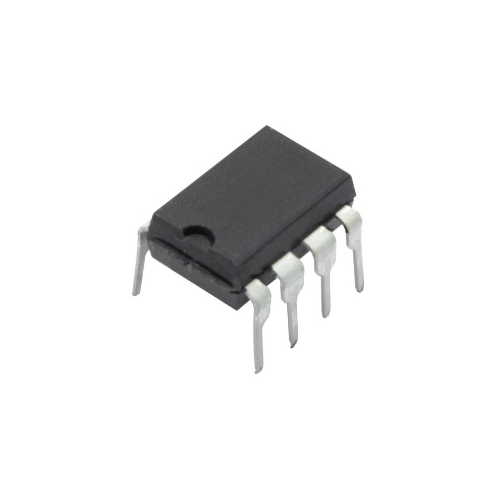
The is a bipolar integrated circuit designed for telephone bell replacement. 8-DIP-300
Two oscillators Output amplifier Power supply control circuit
FEATURES
Designed for telephone bell replacement Low current drain. Small size ` MINIDIP’package. Adjustable 2-frequency tone. Adjustable warbling rate. Built-in hysteresis prevents false triggering and rotary dial ` CHIRPS’. Extension tone ringer modules. Alarms or other alerting devices. External triggering or ringer disable. (KA2410) Adjustable for reduced initial supply current. (KA2411)
Characteristic Supply Voltage Power Dissipation Operating Temperature Storage Temperature Symbol VCC PD T OPR T STG Value Unit mW °C
25°C) (All voltage referenced to GND unless otherwise specified)
Characteristic Operating Voltage Initiation Voltage Initiation Current
Symbol VCC VSI ISI VSUS ISUS VTRG ITRG VDIS IDIS VOH VOL II (PIN 3) II (PIN fH2 fL
Test Conditions See Fig. 2 to GND See Fig. 2 No Load VCC VSUS, See Fig. 2 KA2410 Only VCC 15V KA2410 Only KA2410 Only KA2410 Only VCC -15mA Pin 6V, Pin 7 GND VCC 15mA Pin 6 GND, Pin 6V Pin 6V, Pin 4 GND Pin 6V, Pin 6 GND 0.47µF
Sustaining Voltage Sustaining Current Trigger Voltage Trigger Current
Output Voltage High Output Voltage Low Input Current 1 (Pin 3) Input Current 2 (Pin 7) High Frequency 1 High Frequency 2 Low Frequency
NOTE (see electrical characteristics sheet) 1. Initial supply voltage (VSI) is the supply voltage required to start the tone ringer oscillating. 2. Sustaining voltage (VSUS) is the supply voltage required to maintain oscillation. 3. VTR and ITR are the conditions applied to trigger in to start oscillation for VSUS VCC VSI 4. VDIS and lDIS are the conditions applied to trigger in to inhibit oscillation for VSI VCC 5. Trigger current must be limited to this value externally.






 مقاومت
 مقاومت (SMD (0402
 مقاومت (SMD (0603
 مقاومت (SMD (0805
 مقاومت (SMD (1206
 مقاومت (SMD (1210
 مقاومت (SMD (2010
 مقاومت (SMD (2512
 مقاومت 1 وات
 مقاومت 1/2 وات
 مقاومت 1/4 وات
 مقاومت 1/8 وات
 مقاومت High Voltage Metal Surge
 مقاومت دقیق 1-2 درصد
 مقاومت دقیق SMD
 مقاومت سیمی
 مقاومت شانه ای و Array
 مقاومت شنت
 مقاومت متال اکسید
 مقاومت متال فیلم
 مقاومت وات بالا و آجری
 پتانسیومتر
 مولتی ترن
 ولوم
ولوم ترمیستور NTC و PTC
 خازن
خازن سلف
سلف دیود
دیود آی سی – تراشه
 رگولاتور
 ترانزیستور
 ترایاک و تریستور
 LED و تجهیزات مرتبط
 وریستور
 آنتن
آنتن پیچ و اسپیسر
 پین هدر
 ترمینال پیچی و کشویی
 جعبه و کیس بردهای الکترونیکی
 رله
رله ریموت کنترلر
 سگمنت و ماتریس
 سون سگمنت
 سوكت، کانکتور، فیش
 سیم و کابل
 فن و محافظ فن
 فیبر مدار چاپی – برد بورد
 فیوز
فیوز قطعات صوتی
 کریستال
 کلید، سوئیچ، کیپد
 لیزر
لیزر هیت سینک و المان حرارتی
 ترانس، چوک، فریت، هسته
 میکروکنترلر و پروسسور


نقد و بررسیها
پاک کردن فیلترهاهنوز بررسیای ثبت نشده است.